One output, two sources
A processor constantly chooses between values: the result of an add or the result of a subtract, data from cache or data from memory. The circuit that chooses is the multiplexer, or MUX.
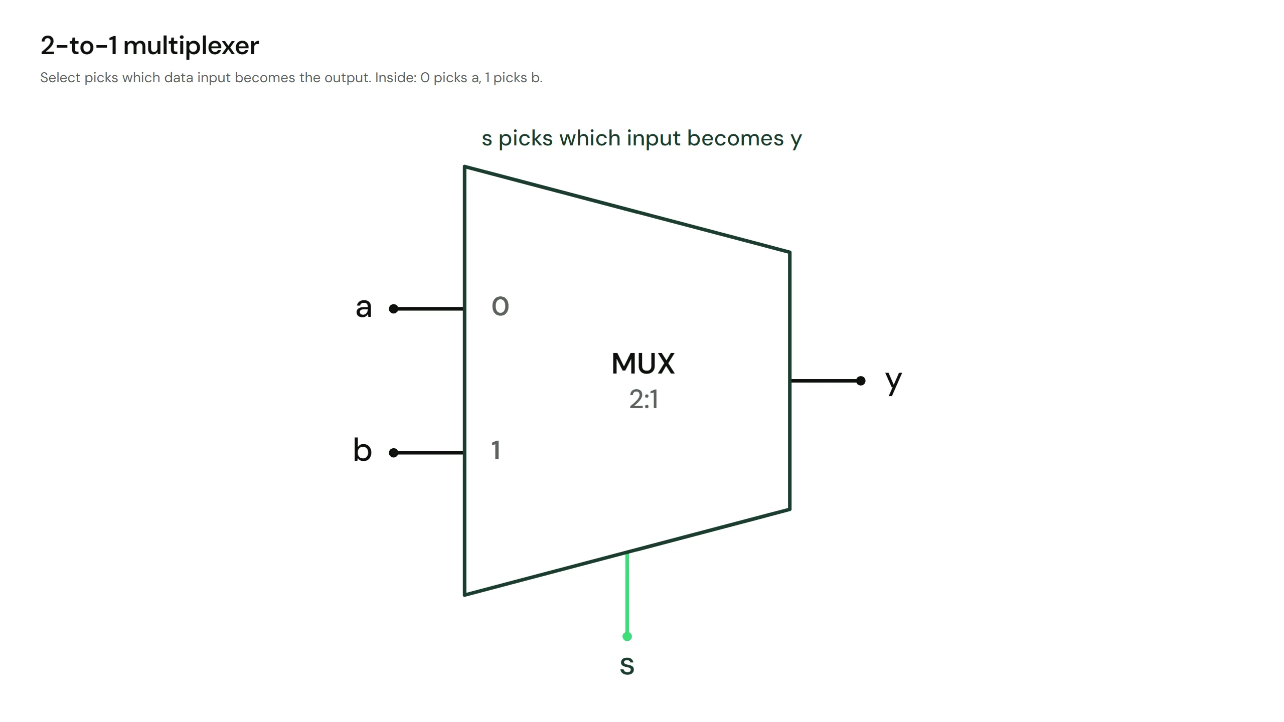
Figure: The trapezoid MUX symbol with data inputs a and b entering the left side, the select signal s entering from below
A 2-to-1 MUX has:
- Two data inputs,
a and b - One select input,
s - One output,
y
The rule: s = 0 routes a to the output. s = 1 routes b.
Drive the switch
This is a live 2-to-1 MUX, built from the gates you already know: one NOT, two ANDs and one OR.
Try it:
- Leave
s = 0 and toggle a. The lamp copies a. - Toggle
b. Nothing happens: b is cut off from the output. - Set
s = 1 and repeat. Now b drives the lamp and a is ignored.
The routing table
Because the MUX ignores one input at a time, its behaviour compresses into two rows:
Written out as a full truth table, the same fact looks like this:
The x means don't care: that input has no effect on that row. Don't-cares are everywhere in hardware design. They mark the inputs a circuit is free to ignore.
From words to Boolean
"Route a when s is 0, route b when s is 1" translates directly into logic: