Three shapes to know
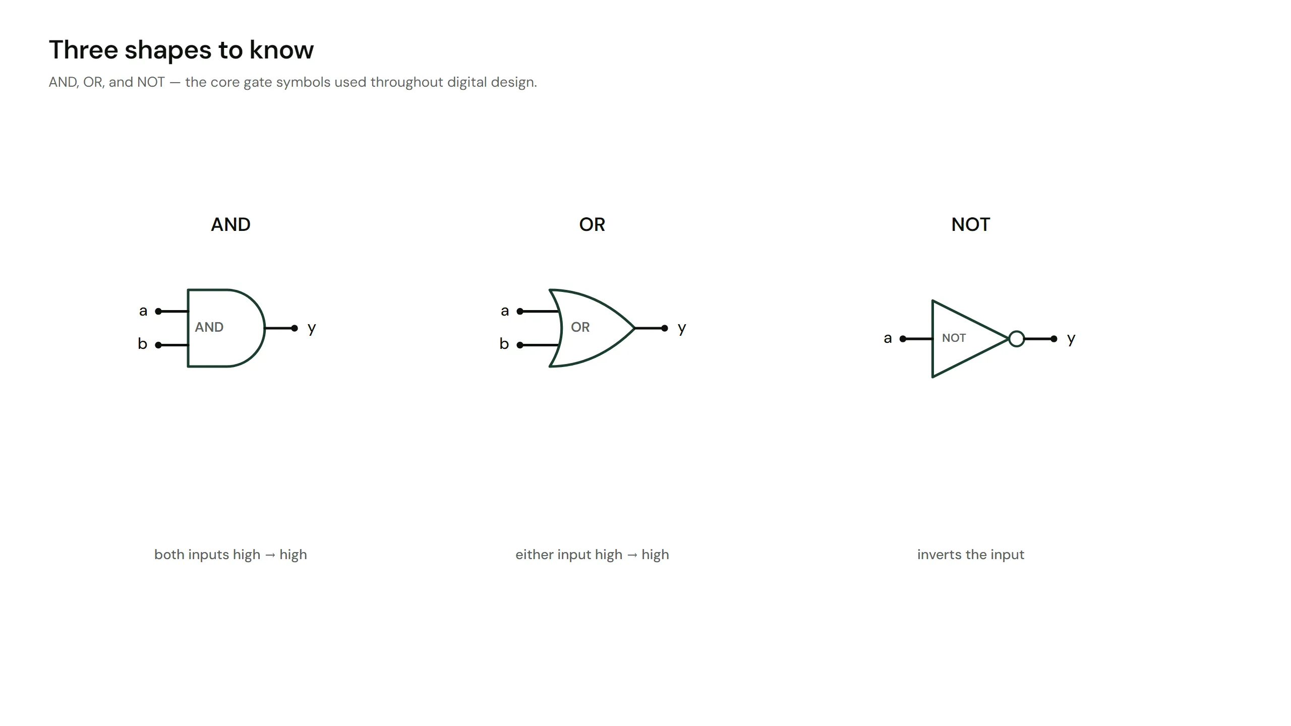
Figure: The three core gate symbols drawn large and labelled: the flat-backed D-shaped AND gate, the curved shield-shaped OR gate
A logic gate takes one or more bits in and produces one bit out, following a fixed rule. Three gates are the foundation:
- AND: output is 1 only when all inputs are 1.
- OR: output is 1 when at least one input is 1.
- NOT: output is the opposite of the input.
Underneath, each gate is a few transistors: real switches in silicon. AND is switches in series, OR is switches in parallel, NOT flips its input.
Poke the gates
The circuit above feeds the same two inputs, a and b, into an AND, an OR and a NOT gate at once.
Try it:
- Set a = 1 and leave b = 0. Only the OR output lights.
- Set b = 1 as well. Now the AND output joins in.
- Watch the NOT output: it always shows the opposite of a.
Every combination of a and b gives one fixed set of outputs. There is no memory and no history here, only the rule.
Truth tables
A truth table pins a gate down completely: every possible input, and the output for each.
NOT:
AND and OR:
Two inputs give four rows. If two circuits share a truth table, they do the same logic, whatever they look like inside.
Reading logic in words
These three gates map straight onto plain English:
- AND is "both": the alarm sounds when the door is open AND the system is armed.
- OR is "either": the light turns on when the switch is up OR the motion sensor fires.
- NOT is "opposite": the pump runs when the tank is NOT full.
Almost every digital circuit is built by wiring gates like these together. Next lesson we meet three more gates, including one that can build all the others by itself.