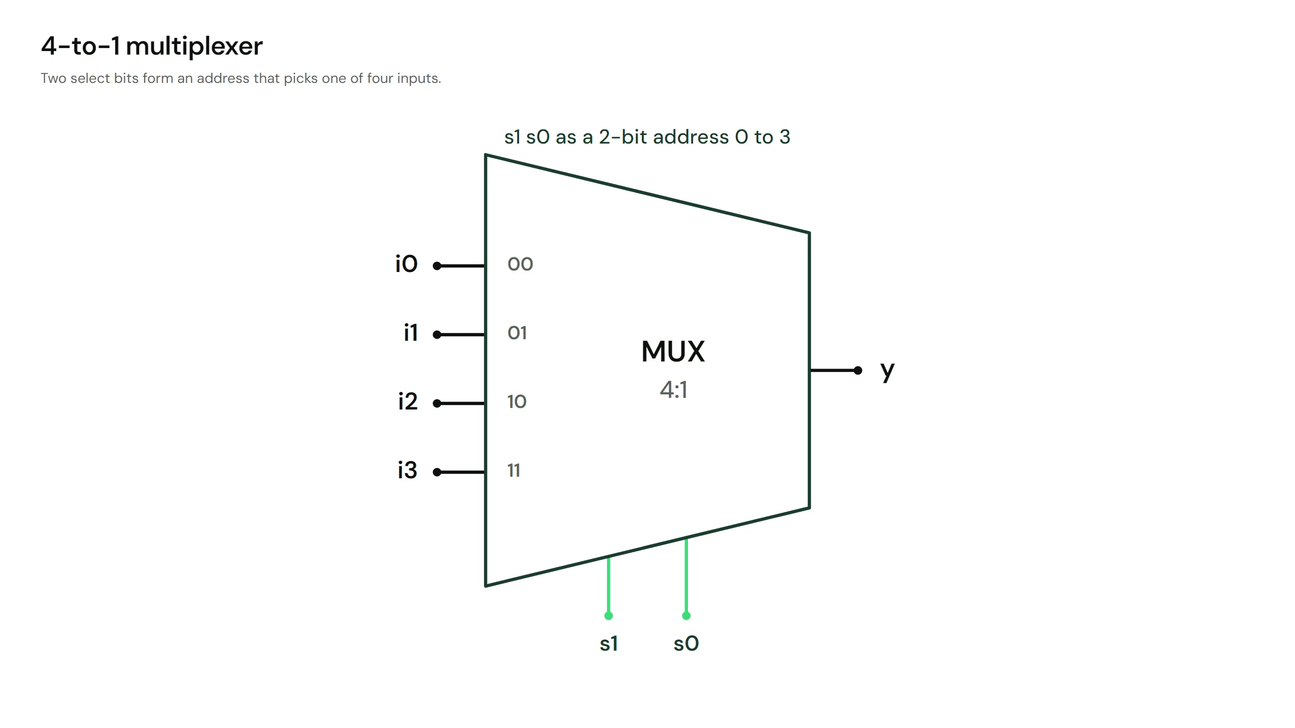
The 4-to-1 MUX in one table
A reminder from Module 2. The 4-to-1 MUX reads its two select lines as a 2-bit address and routes that input to the output.
Figure: A trapezoid 4-to-1 MUX symbol with data inputs i0 to i3 stacked on the left, output y on the right
| s1 | s0 | Address | y |
|---|
| 0 | 0 | 0 | i0 |
| 0 | 1 | 1 | i1 |
| 1 | 0 | 2 | i2 |
| 1 | 1 | 3 | i3 |
The equation is just "y is the addressed input". This time you will not write it as one expression: you will build it the way Module 2 did, from three 2-to-1 MUXes.
Confirm it in the circuit
Set s1 and s0 to an address, then toggle that input. The output follows the addressed input and ignores the other three, exactly as the table says.
Placing a sub-module
Instantiation drops a copy of one module inside another, like soldering a pre-built chip onto a board. Write the module name, a unique instance name, then connect the ports by name:
mux2to1 m1 (
    .a(i0),   // .port_name(signal_it_connects_to)
    .b(i1),
    .s(s0),
    .y(w0)
);
.a(i0) means "wire this instance's port a to the signal i0". The instance name m1 distinguishes it from other copies.
Internal connections
The output of a stage-1 MUX is not a port of the top module. It is an internal wire feeding the next stage, so you declare it:
wire w0;   // first stage-1 MUX output
wire w1;   // second stage-1 MUX output
w0 and w1 carry the two intermediate results into the final MUX. These are the wires that were just lines on the schematic in the hierarchy lesson.
Wire up the 4-to-1 MUX
The mux4to1 module is nearly complete: mux2to1 is defined, and the two stage-1 instances m1 and m2 are wired for you. Add the final instance.
- Instantiate one more
mux2to1, named m3. - Connect its
.a to w0, its .b to w1, its .s to s1, and its .y to the output .